


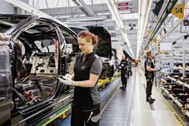


High output and increased complexity mean that Daimler’s highly automated plant in Bremen depends on the most accurate technology when it comes to body-in-white measurement and inspection. AMS reports on how the plant manages the perfect fit and finish
The first thing you notice while walking up and down the seemingly endless corridors of Daimler’s sleek, ultra-modern Bremen plant is the almost complete absence of people. That’s despite the plant employing nearly 14,000 people. Instead, the 850,000-square-metre floor building is populated by over 2,000 robots, all working with surgical precision over the Mercedes SL and SLK roadsters, and all versions of the C-class. The few factory workers you do see use bicycles to move between different areas of the factory: hi-tech and low-tech harmoniously coexist here side by side.
Advances in manufacturing technology now mean that more daring body shapes can make the leap from the designers’ drawing boards to the assembly line. In the notso- distant past, cars had relatively simple, square shapes, with individual parts fitting together along more or less straightforward lines. Now there is far more complexity and the task of inspecting these parts has had to keep up.
The Body-in-white (BIW) Rollout and Process Optimisation Department tackles exactly that task: it is entrusted with the job of inspecting how the various body parts fit together.
More importantly, based on their measurements, feedback is given to the production facilities so specific, targeted adjustments can be made on the tools.
Operational Engineer, Henning Siemers, is involved in BIW measurement and inspection tasks. “Our job is to assure dimensional accuracy of the entire body-in-white,” he explains. “Of course, every BIW consists of many individual parts, and they must all fit perfectly. Our primary duty is to inspect the entire BIW, both individual parts and the whole vehicle, including the panel gaps, and then analyse the data we get.
“Based on the analysis we perform we go back to the production facilities and make adjustments to the tools. We make sure that what comes out is an automobile in which all the parts fit together flawlessly.”
.jpg)
In the past, Siemers’ department relied on hand-operated measurement instruments, but increased complexity and the demands on tolerance have pushed such instruments to their limit.
“Nowadays, cars are much more curvy, with round areas suddenly changing shapes and meeting other panels at all kinds of angles and lines,” says Siemers. “Plus, the much higher requirements for the nearly seamless fit between individual panels, mandates that we work with very tight tolerances.
“With the shapes of our vehicles getting more complex, we have been on the lookout for new technologies that deliver.
Our Quality Engineer, Karl-Heinz Boecker, attends the Control trade show in Sinsheim, Germany each year, and he had his first encounter with the Leica T-Scan system a couple years ago, when it was still just a prototype.
“Based on the announced specs we knew this could be something for us, but we wanted to be positive that the product was truly ready for the market. The primary issue that we saw with many of the other scanning solutions out there was that the software could not keep up with the hardware. Collecting all those points is relatively simple, but what do you do afterwards? We were under the impression that many manufacturers did not award the same attention to the software as they did to the hardware.”
A few months ago Boecker’s team arranged a product demonstration at their facility: a Leica LTD840 Laser Tracker coupled to a Leica T-Probe and Leica T-Scan were chosen – and the system delivered. “It was immediately clear to us that the scanner and software were a mighty combination. We already knew that the scanner was a great sensor, and we were also shown that the PolyWorks suite is a worthy match for it.
The software is very capable and we knew we would be on the right track.”
Since the system delivery, it has been used, among other things, to measure panel gaps, examine part curvatures and inspect reference holes. Siemers has also been busy testing different applications for the system.
“One of the new applications we have found is inline calibration. In the past, BIWs were inspected by being placed inside a grid station and measured using conventional CMM equipment. When you have 150 pallets and want to measure with high tolerances, you’re quickly reaching the limits with traditional methods. That’s why we wanted to be able to measure inline, both the pallets and the tools, and this is where the system will come into play.
Another application of interest to us is the inspection of the entire robot path, and this is something we plan on doing in the near future.”
Asked about what has changed since the implementation of the system, Siemers is very specific: “By relying on scanning I am in the possession of much more useful information. The quality of part analysis has improved. We are able to get to the root of a problem much more quickly and therefore come up with targeted solutions for what needs to be changed. We can, for example, intervene in tool design at such and such point, and change the parameters based on the results we have seen.”

The benefits of using the system are manifold. “We really appreciate the portability. With the equipment I can gather all the information I need in just two to three hours and perform the analysis later. This way, I am not blocking production for too long because the system lets us work in parallel: while one operator is taking the measurements, another one can already be working on sorting out the results.”
The fact that the system is modular is important to Siemers’ team. “We purchased a T-Probe at the same time we got the T-Scan. Tactile wireless measurement is of great value to us when we measure easily twistable parts like the hood. We perform a quick measurement with the probe to get a rough idea about the condition of the part. If we were to start scanning immediately, it would take longer to realise that the hood is twisted. With the probe, collecting just a few points will let us know fairly immediately how we are doing. And we are performing this within the same software, merely switching between the probe and the scanner.”
The probe and scan combination measures within a range of 15m, giving the technicians a volume of 30m in which they can operate. This gives Henning Siemers and his team peace of mind in knowing that should the measurement requirements change in the future, they are well equipped for working in a measurement volume large enough to accommodate several BIWs at one time.
For ThyssenKrupp, based in Bremen, Germany, using vision to optimise quality control throughout the production line has created key advantages in terms of quality and cost-efficiency. The company has a successful track record as a supplier of complex automation technology developing and manufacturing assembly lines for the automotive industry. The company knew they would have to create an added value on their production lines in order to satisfy their customers and maintain global success. They decided to turn to vision technology.
Vision technology has become a central element of the quality assurance system and an important factor in the optimisation of different production steps. A vision solution for any application in challenging industrial environments ThyssenKrupp needs be able to accommodate the wide variety of different product models manufactured by their customers.
 Therefore, the vision system must also be flexible. The company maintains an in-house vision laboratory where staff produce feasibility studies and develop solutions for difficult tasks that require advanced vision applications.
Throughout the process chain, all vision applications are connected as part of the quality assurance system allowing requirements for complete traceability to be met.
Product traceability is, however, only one part of the quality management system. Two-dimensional code readers are used on a production line to trace which part was installed while other readers are used to determine the correct part for assembly. For example, injection pumps of a particular kind are matched to the corresponding injection-nozzle control module. This prevents production errors further down the production line.
Staff at the plant are not machine vision experts, so it is imperative that the vision systems are easy to operate and in that Cognex are well versed. Applications and parameters can be easily adapted by means of simple set-up: the development environment is intuitive and the vision tools are integrated with the production controllers. The In-Sight Explorer development environment is a reliable, convenient solution for programming networks of vision sensors and integrating them into the automation process and into company communications. The fact that they communicate via an integrated Ethernet interface makes them easy to use and is familiar ground for users.