Robots reach for new processes and markets
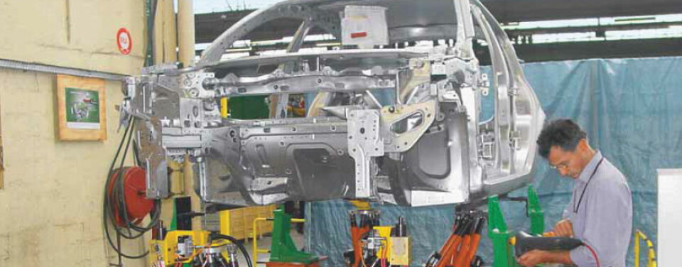
The automotive industry is generally credited with having pioneered the large scale use of robots. Long production runs of identical cars were the ideal field of application for these untiring and reliable workers. Today’s market is increasingly putting automobile manufacturers under pressure to offer customers more choice, while at the same time reducing finished vehicle prices.
To fulfill these apparently contradictory requests, a single line must be able to produce a mix of different models, while ‘learning’ to make new models without the need for a total equipment re-design and preferably without stopping production. Automation suppliers have responded to these demands by making robot cells smaller, more adaptable and easier to install. The new generation of cells can produce so cheaply that they are able to compete with manual labour in low-cost countries, providing manufacturers with an alternative to outsourcing and ultimately raising finished vehicle quality.
A contemporary production line for small cars completes a vehicle every 45 seconds, all day, every day. The naked body shell of a typical car, the so-called ‘body in white’, is typically assembled from between 200 and 400 parts (including those used to make sub-assemblies). Following on from this model, the BIW line (including sub-assembly lines) consumes this number of parts every 45 seconds. Not only must the robots perform flawlessly, but advanced logistics are required to keep the line supplied with parts. Another challenge facing such production lines is one of equipment reusability. In the past, a production line was specifically designed for a single car model. When the time came to introduce a new model, a new line had to be designed and built. Such a solution required considerable investment and lead time, an unacceptable cost in today’s economic climate.
ABB’s flexible approach
As a robot supplier and system integrator, ABB has always recognized the value of making such ‘carry-over’ operations as smooth and simple as possible. The first element of this lies in enabling cost savings by reusing as much equipment as possible. However, while robots and other components may be relatively simple, they must still undergo the same configuration and test cycles as new equipment. To provide greater reusability while simplifying the configuration process, ABB has introduced FlexiBase, a modular robotic test cell in which the robots, controllers and cabling are premounted on a platform. This is set up and tested in-factory for delivey to the customer as a working module, requiring only minimal configuration before it can start production. This is repeated when the cell is reused.
In this way, the reusability of installations has changed from a wish to a recurring theme in plant design, though the carry-over of such installations creates a real challenge for integrators; especially when the new model is to be assembled on an ‘active’ production line. In such a situation, integration of the new model cannot stop or slow down production of other models on the line.
In addition to the associated benefits of a line being carried over from an old to a new model, such flexibility allows a mix of different models to be produced on the same line. The costs of preparing the line for a new model are dramatically reduced as is, by consequence, the risk to the manufacturer if a new model fails to sell as forecast.

The ‘Far East’ challenge
Across Asian manufacturing regions, manually-operated installations are still the norm, as the cost of robots was only acceptable for use with heavy-lifting or accurate operations. ABB has now launched a cost-competitive solution to compete with the running costs of a manually-operated bodyshop: FlexLean.
FlexLean is said to offer the flexibility and reliability of a robotized installation at a price competitive with that of a manually-operated set up. Moreover, this solution requires up to 40% less floorspace. The compactness in the modular solution is an advantage from the point of view of quality and logistics (supply of parts). Its scalability is also of advantage when future car models are introduced.
The basic concept of FlexLean is very simple, building on the FlexiBase principle while increasing its adaptability. The ‘lean’ in the name reflects the simplicity and level of standardization, with the subsequent cost reductions that it enables. This makes it competitive with manual labour in low-cost countries, while delivering savings over other robot solutions in higher-cost countries. The system offers greater set-up flexibility as each cell is a standalone system. During startup and commissioning, staff can work on isolated cells as each is controlled by a complete set of automation modules, including a PLC and a man-machine interface. These modules communicate through a threelevel Bus system: FieldBus for real-time process, SafetyBus for critical I/Os and Ethernet for generic information. The standardization of products used in the cell not only returns cost reductions, but can be a big advantage for control systems. Complex PLC programming operations are no longer required as every component of the cell is known and the required PLC code is written to cover all systems. However, one part of the automation still remains variable – the part that is related to the manufacturing process itself.
Space at a premium
Today there are automotive production lines that have the capability to produce up to eight different models. In addition to this, further variants are possible through customisation. Each car is defined before production starts and this information is fed to the cell controllers as and when it is necessary, allowing for the addition of customerspecific options on the line. Manufacturing has come one step closer to the dream of combining mass production with made-to-order individualization. Innovations serve to make robotics easier to setup, use, and re-use, while cutting back constraints such as space requirements and time lost during operations. These advantages are helping position robots in increasingly challenging applications.
Success through simulation
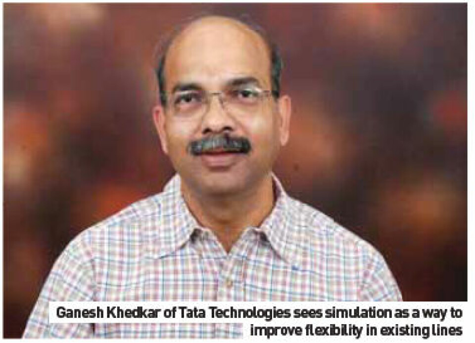
Tata Technologies acts as an integrator, designing, specifying and installing robot systems for OEMs and Tier suppliers. Though they do not manufacture robots, they have one of the largest teams working in the sector, with almost 4,000 robot simulations to their credit. AMS spoke to Ganesh Khedkar, Associate Vice-President, Engineering & Design, about the company’s activities supplying robot and conveyor technology. “Typically we work in specifying and building BIW lines for OEMs, this makes up about 80% of our work in this area. We also have some applications in the final assembly area, such as windshield, window glass and of course, material handling. Another area where we have worked with OEMs is in the paintshop.”
Take a look around a modern automotive manufacturing plant and it is clear that automation is concentrated in BIW and paintshop. The predicted rise in automating trim and final assembly, using robots for the varied intricate tasks in this area, has not come to pass as Khedkar agrees: “In final assembly we have seen some automation, but it is mainly confined to material handling, using powered handlers for instrument panels and seats – devices to assist the human operator, not to take over. The focus in assembly is mainly on logistics and related automation and concentrates on just-in-time (JIT) and just-in-sequence (JIS).” Powertrain assembly is an area that could potentially benefit from increased automation, including operations where heavy and awkward components are lifted and shifted for final assembly, but Khedkar notes that there are difficulties in this area. “In powertrain, we see robots typically deployed to lift and load components onto machines, but not in assembly. This is due to space being such a premium in powertrain assembly, everything in the zone is relatively small and narrow.” Of course, customised manipulators, such as power assistance ‘arms’ to move heavier components for operators, are much more common.
In BIW, the relative responsibility of the integrator varies between using the customer’s specified automation suppliers and being charged by the client to design and specify all parts of the production cell or section of production line. Khedkar: “For us, a job could start with a customer wanting to plan a new line from scratch, typically in a greenfield project, where we would come in, design a rough layout and plan the stations. Then the main concern is the distribution of weld spots. In fact, I would say that weld spot placment is the key ‘backbone’ of BIW process planning.”
The construction of a BIW line is one of the most complex planning tasks in plant design; the stations are large, very high value and use very bulky and heavy machinery that a company would only want to install once. Sequenced spot weld stations are planned not only to address the incoming material handling considerations but also the progress through initial ‘fixing’ or geometric spot welding and the following re-spot weld line. Khedkar points out that a technical decision must be made as to which spots are to be welded first on the various sub-assemblies: “Deciding which welds to make first is a critical technical decision and a planner must try to eliminate any distortion and plan for the fixing requirements of the following weld operations. Once we have made the initial station configuration, which we call the first level concept process plant, we then bring robots with weld guns and simulate to see if all spots are reachable, all in a digital environment.
“Weld guns are the inventory customers want to keep at a minimum. It’s also possible that they would specify weld guns from existing equipment, or at least from a known partner supplier.” At this point line balancing comes into play, adjusting the cycle time of the weld operations to match the projected timing of the total BIW line. Integrators will create a spot weld matrix, a three-dimensional ‘map’ of the spot welds to be made and the guns involved.
This allows the planner to decide which of the available weld guns are best-suited to each operation, allowing them to ‘shift the spot’, changing the weld sequence within a station or moving that weld to the next station. This matrix and the subsequent decisions can be modeled in virtual form using workcell simulation programmes such as Delmia from Dassault Systemes or Technomatix Robcad from Siemens. But as Khedkar says, some line builders still rely on physical models. “Some companies use solid models of cardboard or other materials, but this does not take advantage of the technology available, It is very inefficient, from the perspective of time usage.”
Virtual preparation for succesful integration
With the comparatively high cost of robotic automation, it is obviously necessary to make sure that the equipment is functioning at maximum efficiency and productivity in order to realize optimal returns on the capital investment for both new manufacturing systems and mid-cycle changes to existing lines. Older, manual methods are no longer sufficient, with updates requiring multiple experts working in a non-collaborative workflow. This can result in improper installation and drive a variety of costly manufacturing changes.
Workcell simulation tools give planners the ability to develop, simulate, optimize, validate, and off-line program multi-device robotic and automated manufacturing processes, all in the context of configured product and resource data. These full-action, three-dimensional mockups of complete manufacturing cells and systems provide a platform to optimize processes and calculate cycle times throughout the various stages of the development timeline, from concept through to implementation.
Khedkar: “Using the simulation tools, we can now virtually plan weld operations with 90% accuracy. The next planning stage is to give the modeled information of the initial process concept to the fixture designers. Once the fixture design has been made, the second stage is to integrate the fixtures into the matrix, to see that none of the fixtures foul any weld gun movement. Any corrections are fed back to the fixture designers for correction.” Sequencing of the weld pattern is the next step; choosing the robot sequence for maximum speed and minimum repeat motions; optimizing robot usage is combined with fouling tests.
The final stage of the virtual planning process is in off-line programming, where the finished program is ‘harvested’ from the workcell simulation programme for uploading to the robots on the shopfloor. Robots are then run through the sequences and the results are typically very close to production-ready, as Khedkar says: “This means we do not have to do any further trials and we can start running the operation very quickly.”
One benefit of ‘computerised’ programming over its manual equivalent is that the simulation programme will often find a better movement sequence than could ever be developed by a human operator; the system can uncover a sequence that, while appearing convoluted – even illogical – to the human eye, is more efficient than that choreographed by moving the robot one action at a time by joystick or another manual control method.
The main part of the robot cycle (90%, as mentioned earlier), has now been modeled accurately; the remaining 10% requires manual intervention. This is mainly to compensate for the behaviour of the flexible cables and hoses attached to or running through the wrist of the robot arm which, due to their unpredictable flexibility, require on-the-robot testing and adjustment.
Local sourcing
While complex robot and controller technologies are still the province of the international supplier, who is often the global choice of the end-customer OEM or Tier supplier, jigs and fixtures can, by their straightforward construction, be made almost anywhere. As such, the trend is to move towards more local sourcing. Main framing stations and other critical geometric stations would always be commissioned from the line supplier or from the OEM’s traditional global partner but feeder sections of the line, such as door lines and bonnets, are often equipped with locally-sourced fixtures.
Wireless control and flexibility
The automotive manufacturing shopfloor is quite hostile to radio signals used in the wireless control of robotics and

conveyors and indeed, most production equipment. This is especially so in complex, ‘organically-grown’ plants, where automation is added to existing, and often quite old, production floors. Khedkar feels that wireless technology has not matured to the extent where it can be used outside new, stand-alone production units. “It will take some time for wireless to reach the power and sophistication that can cope with the hostile environment found in many plants.” On line flexibility for the ever-changing segment demands of a market like India, Khedkar has some sage observations: “New lines for new platforms are a difficult choice for carmakers; it is a luxury that very few OEMs can afford. Carmakers would like to make existing lines as flexible as possible, primarily because no-one knows how the market will move; what will demand be for various segments in 20 months, typically the planning period running up to start of production.
“As an example, one of our customers has a single line in place and they are looking to add a new model. They want to know if the new car can be made on the existing line. This makes for an interesting exercise on robotics usage; BIW is the most integrated process in automotive production when compared with powertrain, paint or a final assembly. “We can load the design of the new car into the simulation program and see where it can be accommodated and where it cannot. This also means that during the design stage of a car, we can fully test its manufacturability using virtual modelling and simulation.”
Tight timelines
As in other areas of automotive manufacturing, BIW has very tight schedules in regards to introducing new models and ramping-up lines. Tata Technologies was commissioned by a Japanese OEM to ready a complete line for a new model to be produced in Hungary, all within a two-week shutdown. Khedkar: “The timeline was not flexible, the cost of overrunning the two weeks would have been prohibitive. To avoid this, we did all the simulation on the existing model, input the parameters of the new model and made off-line programs for proving on the line when the plant came back from holiday. We did all this in India and sent the programs to Hungary. Though we had provisioned the onsite engineers for support, this was not required.”
Cleaning the casting die
Various processes are used to clean casting dies. The most common uses cullet, or glass bead. Other cleaning agents include various chemical products, water or dry ice. In foundries, the die lubricant applied before the casting process has to be removed to avoid contaminating the body and chassis pieces being stamped. It is a dirty, heavy and time-consuming job. Depending on the complexity and size of the die, the time needed to manually clean a complete gravity die for production of chassis components can be up to 50 minutes.
In the light alloy centre at Volkswagen’s plant in Braunschweig, Germany, cullet was used for cleaning gravity dies. In examining the options for an automated system, it was realised that any system would need to clean form geometries in relatively inaccessible areas. For this reason, the decision was made to stay with cullet as the cleaning medium. After comparing different systems, Reis Robotics was chosen as automation partner for implementation of the system. An intense period of co-operation with the operators of the light alloy centre followed, which after a planning and commissioning phase of only six months, saw the system enter operation.
Safer process for safety-critical parts
Volkswagen’s Braunschweig works employs approximately 6,500 people, 250 of which are in the light alloy centre, which opened in 2002. The product range comprises auxiliary frames, swivel bearings and wheel carriers, all made from light metal. These components are produced both by gravity die-casting and by CPC back pressure moulding.
As these casts are considered safety-critical, with every process step and production parameter carefully monitored. It takes approximately 24 hours for a component to pass through the various quality checks between the foundry and sign off as a completed part. The daily melting capacity is 192 tons of aluminum, which is cast into 40 gravity dies. The dies forming the components have to be carefully cleaned on a regular basis.
Before pouring the liquid aluminum into the gravity dies, some are treated with die lubricant. Once a day, this has to be removed from the gravity die using the automatic cleaning system from Reis. If the die lubricant is not completely removed before a new application starts, casting defects may result.
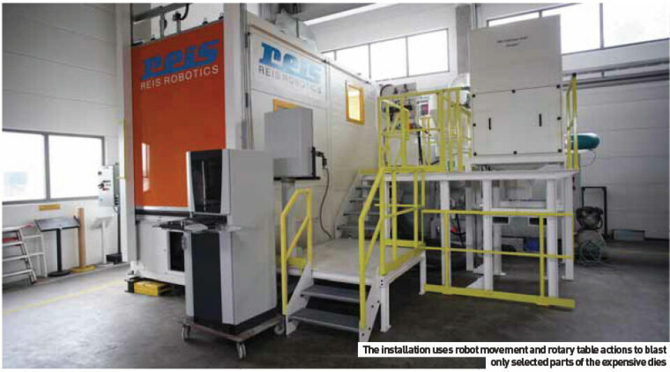
The system consists of a blast room where the cleaning process itself takes places, and a robot work envelope. Robot and blast room are separated by a highly-flexible blast collar to prevent the blast agent from causing damage or increased wear. The operating components and the automatic blast medium conditioning are installed on an operator platform outside the cabin.
The gravity dies are loaded by a fork lift through an automatic door at the blasting station. The gravity dies are paired, with upper and lower moulds on racks. The moulds are deposited on a robot rotary table with universal racking designed to allow cleaning of all areas of the gravity die moulds.
The cleaning process itself is carried out with a highcapacity, fully-robotized pressure blast nozzle. This procedure is supported by the complementray positioning movements of the robotic rotary table. After the cleaning process, the component is further blasted by an integrated air nozzle to prevent blast agent being carried out of the blast room on the gravity die.
New tools for the man-machine interface
Programming of modern industrial robots is mainly done at the robot with a portable teach pendant using a teach-in procedure. In order to make programming more intuitive, Reis has integrated a graphic user interface into the robot control, ROBOTstarV, which is based on Augmented Reality Technology.
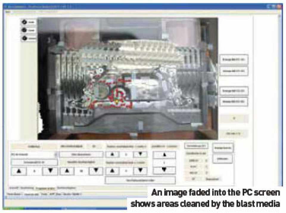
Augmented Reality essentially translates to ‘extended reality’ and represents a new method of man-machine interaction. Information from the robot control, i.e. positions, paths, program data, is ‘faded’ into a real camera picture and at the same time displayed on a PC monitor. The functionality of Augmented Reality is integrated into the operating area based on graphics generated by ProVis-AR (Programming and Visualization in Augmented Reality), with control made via a connected PC. Since the operation functions on freeware internet technologies, there is no procedure-specific software to install. After calling the homepage for the robot, the user interface is available once it is loaded from the control to the PC.
The robot control has direct access to a high-resolution camera installed in the system. The operator sees a picture on his monitor and can judge the amount of gravity die soiling. Using a mouse, the worker can select areas to be cleaned, at which point the robot control selects the stored blast program before fading in the stored path positions on the monitor.
When the blast process is finished, a new image of the blasted gravity die is automatically generated and displayed; the most important operating elements are faded in to help the operator decide whether:
• the gravity die is clean enough
• reblasting is required using identical parameters
• reblasting is required with changes to the blast intensity and/or position shift.
