


Robots equipped with 3D smart sensors from LMI Technologies are aiming to take production processes to a new level
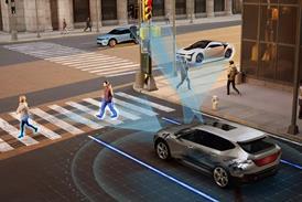
Integrating a robot with a smart 3D laser sensor provides a flexible, programmable measuring system. With today’s smart sensor and robot technology, programmable measuring robots are being used to automate a wide variety of processes on the production floor. Typical uses are for programmable measurement of large objects, such as automotive bodies and sub-assemblies.
In summary
• Integrating 3D vision sensors with robots can provide programmable, plant floor inspection systems.
• In-line robotic inspection systems can inspect a mix of different models, with minimal limitations on cycle time.
• Off-line robotic stations can replace multiple inspection check fixtures with dramatic cost savings.
• Fully integrated robotic inspection stations provide the most effective solution.
Robots and sensors
The programmable nature of robots allows multiple programs to be available, even for scanning and measurement of single-part geometry. In normal production, selected critical points can be measured for process monitoring in order to maintain required production cycle times.
During the pilot phase of a new program, where cycle time is not generally an issue, the robot can be programmed to inspect many more points on each part, providing high-density data to assist in rapidly tuning the assembly process to achieve a shorter launch time. This high-density data can be used during production, for example, being run during breaks in production where longer cycle times for measurement are available.
3D vision sensors for robotic measurement and inspection
While a measuring robot could potentially use a contact sensor, similar to the mechanical probes used on a coordinate measuring machine, non-contact vision sensing provides freedom from probe wear and part deformation, and eliminates downtime from probe crashes. Also, touch probes are relatively slow in comparison.
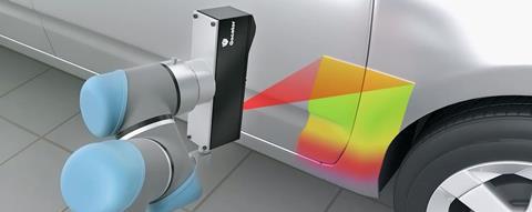
Using a 3D laser vision sensor also provides maximum flexibility to measure a variety of characteristics, such as feature (hole or slot) location, standoff, and edge locations. In addition, 3D laser sensors offer high-speed image acquisition and analysis to minimise the time required for each measurement point. Typical sensor cycle times are 150 to 300 milliseconds, depending on the type of measurement. Each measurement cycle may provide multiple data points.
Sensors mounted on robots are subjected to significant dynamic loads due to robot acceleration/deceleration and vibration, as well as impact loads due to programming or robot path errors. For measurement stability, smart sensors have integrated optics housed in a rugged, sealed package that is manufactured from a single block of material.
Sensor/robot integration
Creating a measuring robot requires a number of elements other than just mounting the sensor on the robot end effector. The vision image processing algorithms must be integrated and programmed in conjunction with the point programming for the robot. Coordinate transformation between robot and sensor coordinate systems is required.
3D smart sensors are easily mounted on a robot end-effector using built-in hand-eye calibration to determine the sensor coordinate transformation to robot coordinates. This allows the position and orientation of an object detected by the sensor to be communicated directly to the robot in order to perform assembly-based tasks (e.g. roof/windshield insertion).
The sensor also provides the tools to locate parts, and communicates these measurements over strings to a robot controller using a TCP/IP socket. Critical X-Y-Z and angle information is communicated to the robot for use in vision guidance, inspection, and pick-and-place applications. The process of interfacing the sensor to the robot requires no additional external software or PC. Everything is onboard the sensor and working in a tightly integrated interplay between seeing, thinking, and doing.
Robotic systems implementation: Off-line
Robotic measuring systems are implemented off-line in a number of applications to provide programmable measurement. The main difference between this system and the traditional coordinate measuring machine is that the robotic system is placed on the plant floor, not requiring a clean, temperature-controlled environment. Doing this, close to the manufacturing operations, eliminates delays in measuring parts and in providing feedback to manufacturing.
For example, in an automotive stamping shop, a single robotic system is installed for using off-line as a replacement for multiple mechanical part-checking fixtures.
Each closure panel typically has 30 to 40 points programmed for inspection. All closure panels, both in-process and in final form, can be inspected by the single robot station. A simple holding device is used to position each part, with virtual fixturing used to correct for minor part location errors.
The off-line robotic check fixture system is economically far more attractive than the cost of a full set of dedicated hard-check fixtures. Reprogramming for the next model again is simple. Much less floor space is required and the inspection points can be changed at any time with simple reprogramming.
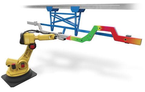
Another cost effective implementation of robotic inspection systems off-line is the programmable measurement of the mechanical support structure for automotive instrument panels. These parts are made in several configurations even for a single vehicle. Variations often include left- and right-hand drive versions, and a variety of other geometries based on optional equipment. Traditionally, a separate measuring device was required for each model. With a single robotic station, one system replaces multiple check fixtures, and model change is accomplished by simple reprogramming.
Robotic systems implementation: In-line
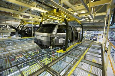
The in-line use of robotic-based flexible inspection systems is rapidly growing in assembly operations. Flexibility in inspection is an important issue as assembly lines become capable of building multiple models. A typical plant may use robotic inspection for the body-in-white, underbody and other sub-assemblies, all implemented in line for 100% inspection. Each inspection station typically consists of one or more robots, with each station having a data display terminal used to collect and display information, combine data from multiple robots in a station, and send the data to the plant network.
Generally, both the body-in-white and underbody inspection stations are implemented with four robots and both are in-line 100% inspection stations. With the robotic solution, a mix of different models can be accommodated. In one example, each style of body-in-white has 88 inspection points, with multiple styles resulting in a total of 200 unique points. The four-robot system then replaces 200 fixed sensors in a frame in the traditional fixed in-line gauge frame. The robotic solution is more economical in terms of acquisition cost, and offers easy conversion to the next new model with simple reprogramming rather than physically repositioning the fixed cameras.
For sub-assemblies, such as the firewall and rear compartment, stations are also mounted in-line for 100% inspection. Each of these stations checks approximately 40 points. Reach and cycle time requirements in these stations are met with two robots in each station. Cycle time per point is dependent on the distance between each point, with robot movement being a contributor. Typically, an average time per point is two to three seconds. Ideally, where multiple stations are implemented in a plant, sending information to the plant network is key, so the measurement information is available to all those involved.


1 Reader's comment