


Mould and die manufacturers reveal the latest solutions deployed to ensure quality control remains paramount
There are not many processes in the automotive supply chain where accuracy and precision are more fundamentally important than in toolmaking. However, the dimensional and geometric assessment of tools, be they for pressing or moulding operations, is far from straightforward due to features such as complex freeform curvature, blended radii and meticulously applied draft angles.
This point has not eluded Tianjin Motor Dies, where quality control throughout the die production process is paramount to ongoing success. Founded in 1995, Tianjin Motor Dies operates ten die shops, nine of which are located in China and one in Germany. The company serves nearly all of the former country’s automotive sector’s major domestic and international OEMs.
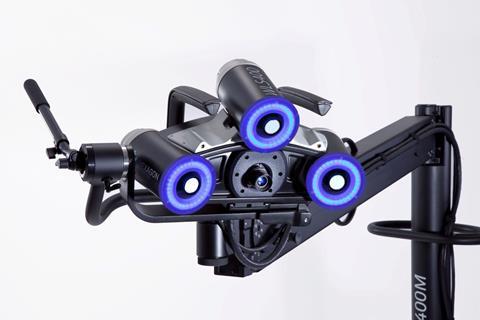
Tianjin Motor Dies’ partnership with Hexagon Manufacturing Intelligence and its forerunner businesses began over 20 years ago, when the company was still a state-owned enterprise. At the plant in Tianjin alone, five of the company’s die shop measuring rooms have been equipped with DEA gantry CMMs, mainly for inspecting dies, fixtures and other die-making equipment. Among the latest investments is a Hexagon WLS400M white-light measurement system, which again is used in die processing.
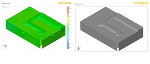
“The shape of the die is not exactly the same as the shape of the final product, as the sheet material will always spring back to a certain degree,” explains founder and chairman Chang Shiping. “Therefore, any quality control measures applied to the die equipment must be precise; whether the die equipment meets specifications depends on the quality of the final product, the stamped sheet metal.”
White-light measuring systems
“Today, quality requirements for die-manufactured parts have become higher,” adds Shiping. “In order for us to enhance measurement efficiency and realise full control over the dimensions of curved surfaces and smaller details, we began using non-contact white-light measurement systems. Importantly, these systems are quick at processing data and comprehensive in analyses. They have contributed greatly in our efforts to enhance testing efficiency with regard to die parts.”
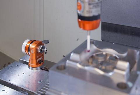
Another company specialising in high-performance stamping tools is Fritz Stepper, which produces up to several billion contact parts per year, predominantly for the automotive sector. For quality assurance, the tooling expert has been relying on technology from Alicona for many years.
Stepper’s tools often produce up to seven plug connections simultaneously at 2,300 strokes per minute. For Marcel Heisler, head of laser ablation and high-speed cutting, one thing applies above all: “We need to measure, measure, measure; after all, the automotive industry demands maximum precision and productivity.
“We use Alicona for continuous quality assurance and further development of our tools with regard to material, surface quality and accuracy. This is only possible with absolutely reliable measurement results.”
Since 2010, Fritz Stepper has been using Alicona’s Focus-Variation measuring systems. “Before, we had massive difficulties measuring the steep flanks, smooth surfaces and different reflection properties of our tools,” explains Heisler.
Defining measurement in CAD data
In terms of increasing efficiency through automation, Stepper has further plans with Alicona. The optional connection of the company’s automation software to an existing CAD/CAM suite allows the integration of measurement technology as early as the design phase, by defining measurement routines in the CAD data set of a component. A simulation provides a preview of the inspection process to be carried out, thus supporting reliable measurement planning.
“We expect massive time savings,” states Heisler. “With the CAD/CAM connection, I no longer need the measuring system to teach-in my measurement operations; this can be transferred to another workstation. As a result, we will be able to use the measuring device 24 hours a day, seven days a week, without any interruptions to manufacturing.”
The requirement for accuracy and precision is no less when it comes to injection mould tools. Here, the measurement of parts is intrinsically linked to mould measurement. Although the mould may check out as dimensionally correct, the part can emerge differently, typically due to warpage and/or shrinkage. A case in point can be seen at Oechsler, based in Ansbach, Germany, which is leveraging the benefits of an optical 3D measuring system.
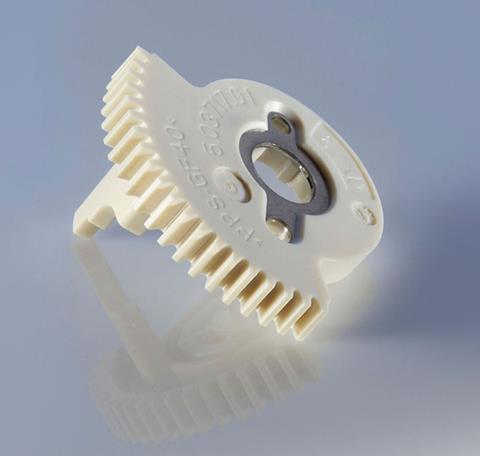
One of Oechsler’s principal inventions – and now one of its biggest sellers – is an actuator for electronic parking brakes. The core of the actuator is a gearbox made of plastic. Indeed, hundreds of different plastics are processed at Ansbach, almost 80% of which are fibre-reinforced.
“Such materials have a tendency to warp, especially in some housing products with thin walls,” explains Dr Marco Wacker, head of technology and innovation. “The measurement of these housings with tactile systems kept causing problems. Changes made to the mould tools were not always reflected in the measured data. In addition, tactile measurement reduces 3D measurement to an abstract representation of binary or ternary points in a table. Then, designers have to implement the results into their 3D system. It no longer made sense in the digital age.”
3D scanning
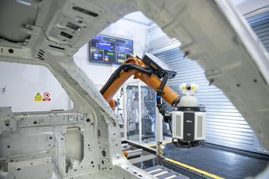
The search duly began for an alternative method, with the company opting for GOM’s ATOS Triple Scan, which uses 3D scanning featuring fringe projection. A detailed image consisting of millions of measuring points can be recorded within a few seconds as part of a non-contact process. GOM’s software computes 3D object coordinates for each camera pixel. Notably, the calculated polygon mesh describes freeform surfaces and regular geometries that can then be aligned with the drawing, or directly with the CAD data set as part of a shape and dimension analysis. Compared with tactile measurement, the entire part surface can be scanned very quickly, without blind spots.
Once Oechsler gets the green light from the customer, the tool is verified and a flow simulation calculated using Moldflow software from Autodesk. The simulation is said to deliver excellent results for most of the materials that Oechsler uses, including with regard to warp predictions. “This is why we build our tools with a slight warp now,” Dr Wacker explains. “Furthermore, so we can become even better over time, we’ve created an internal control loop.”
Firstly, an expert at Oechsler enters process parameters into the simulation system based on their experience. The operator at the injection moulding machine accepts the data, modifies the parameters if necessary, or makes the tool based on their own experience. In any case, the plastic product is measured using the GOM system, with the results returned to the simulation. The goal is simple: feedback until the necessary accuracy has been achieved.
“In cooperation with the toolmaker, I create a correction report that is implemented in CAD, before the tool is corrected and re-sampled,” explains Birgit Hauf, a member of the R&D department and in charge of the GOM system. “Thanks to the improved information that the GOM system delivers, it now takes only three feedback loops on average for new parts. With tactile measurement, it took a lot of effort and multiple iterative loops to slowly achieve the final tool contour.”
Dealing with thermal drift
The latest innovations in metrology are also facilitating progress at UK injection mould specialist BK Tooling, which serves markets that include commercial and industrial vehicles. Typically, the company’s moulds are for research, development and prototype work. Components for the moulds are machined using high-speed CNC vertical machining centres (VMCs), where another known challenge to toolmakers has to be kept in check – thermal drift.
All machine tools are subject to thermal effects, generated by their operation and changes within their environment. For three-axis VMCs, the greatest effects typically occur in the Y and Z axes. For example, high-speed machining coupled with long cycle times can result in thermal drift of up to 100µm in the Z axis. Uncorrected, this kind of variation causes positional errors, leading to incorrectly machined parts. BK Tooling typically experiences movement of 15µm. Therefore, when working to tolerances below ±10µm, and taking other variations such as tool wear into account, effective process control is vital.
Engineers from metrology specialist Renishaw were tasked with introducing measures to increase automation and eliminate manual intervention. The adoption of automated in-cycle probing using Renishaw Primo probes enables BK Tooling to track the thermal growth of machine-tool axes and automatically update offsets as required. Ultimately, the probes allow the company to maintain an accuracy of ± 0.01mm, and avoid scrap and rework.
To download the full AMS January-March 2020 digital magazine click here.


No comments yet