


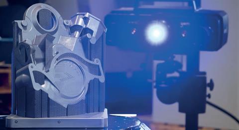
GOM’s work on the engine front cover of a 1967 Cadillac Eldorado ably demonstrates the value of optical metrology in the 3D printing process
Leading companies have already made the switch to optical metrology for quality assurance in traditional manufacturing processes such as plastic injection moulding, sheet metal forming and casting. As additive manufacturing technologies are maturing, more and more companies are introducing optical metrology into their processes.
Additive manufacturing is no longer used for prototypes only, but also increasingly in applications for functional parts. The biggest challenge with functional 3D-printed parts is to prove to the end user that the parts are reliable and that their functionalities meet exact requirements in terms of dimensional quality, tensile strength, hardness, wear-resistance, heat-resistance etc.
Using optical techniques for functional testing, process control and quality control offers many benefits, especially for 3D-printed parts, which are often complex, highly customised and have free forms.
The business case at Rolf Lenk Werkzeug- und Maschinenbau GmbH
A practical example is the partnership between GOM and Rolf Lenk Werkzeug- und Maschinenbau GmbH. Rolf Lenk uses an ATOS 3D scanner in its additive manufacturing processes. In this example, the 3D scanner was used for measuring an engine front cover of a 1967 Cadillac Eldorado, which later was printed in 3D.
While manufacturing the engine front cover in 3D at Rolf Lenk, technology from GOM made sure that an exact replica of the original could be produced and any geometric variation could be identified and corrected during the process.
The 3D-printing production process
At Rolf Lenk, optical metrology is not only being used for quality inspection at the end, but throughout the whole process. There are even some applications that take place before the actual print. Inserting optical metrology in different steps of the 3D printing process leads to better monitoring and therefore faster intervention times when something is wrong, and enables a deeper understanding of the different steps.
Before the print: 3D testing for the right material selection
In automotive applications, titanium is usually the preferred powder for functional parts due to its superior mechanical properties and thermal and corrosion resistance. But titanium has one big drawback, the price, and that is why researchers are investigating specialised aluminium alloys.
If they can ensure that the mechanical properties match those of titanium, this could lead to huge cost reductions, because aluminium alloys not only enable faster building speeds, but they are lighter, allow faster post-processing and have superior machinability.
The ARAMIS 3D testing system from GOM is ideally suited for materials research. The analyses of, for example, tensile, compression or bending tests provide information on material characteristics, but the system can also analyse the behaviour of components under load. These results form the basis for product durability, geometrical layout, reliable numerical simulations and their validation.
In general, material developments are necessary to support the high volumes in the automotive industry. 3D testing is the right tool for analysing dynamic tests in 3D and getting full-field and precise feedback as well as for complete material analyses, from general strains to specific cracks and structures.
The 3D model
Once the user has made the right choice regarding the 3D printing process and material, a 3D model is needed. ATOS 3D scanners from GOM can generate a 3D point cloud which can be send to the printer or, due to the high detail and precision of the data, can serve as a good start to easily further design the 3D model.
At Rolf Lenk, the broken engine front cover was scanned to reverse engineer it to a new part in CAD. Reverse engineering in CAD can be a time-consuming process, but the clean and accurate data of the scans made the process easier compared to other methods or scanning systems.
GOM Inspect, a software that can be used with the ATOS scanners or other measuring systems, has mesh editing functions that can make the STL printable, even without reverse engineering. To make the mesh watertight, the ‘Close Holes’ function can be used and with a few clicks wall thickness and angles can also be measured.
Reducing stress
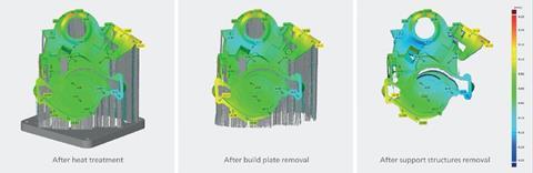
The most common way of reducing stress in metal 3D printing is by applying a heat treatment before removing the part from the base plate. Internal stress can cause the part to warp, shrink or curl, so it is important to minimise it as much as possible.
With the ATOS scanners, it is possible to scan in between the individual steps after printing the part and see exactly how and when the part deforms.
Measuring the engine front cover at Rolf Lenk before and after heat treatment, following removal of the part from the plate and removing the support structures, lead to some interesting insights. Looking at the surface comparisons in figure 1, it became clear that after heat treatment, the part slightly curled due to elongation of the bridges. After removing the build plate, the part warped due to springback and some more warping occurred after removing the support structures due to tension.
Tracking how internal stresses are deforming the part provides information that can be linked to the production process offering valuable feedback about the design or build orientation of the parts.
Post-processing
Machining or surface finish can have an influence on the dimensions of the part as well, and this can also be measured. Before machining, a surface defect map of the part can be generated in GOM Inspect to evaluate exactly if machining is necessary.
If machining is necessary, clamping a free-form 3D-printed part inside a CNC machine and defining the zero point can be challenging, time consuming and inaccurate. By scanning the part in a clamped state, the definition of zero points and the alignment can easily be done in GOM Inspect and communicated to the CNC milling machine.
Final part
Due to the full-field measurement of the printed part and the recognition of process-related influences, corresponding countermeasures can be taken such as, for example, the provision of expected deformation.
When measuring multiple parts, the GOM Inspect software can produce a statistical evaluation for machining allowance control. By analysing process capability and process performance, it is easy to verify if the 3D printer is still calibrated and stable.
ATOS scanners do the final dimensional surface checks and, recently, a CT scanner was added to GOM’s portfolio for measuring internal geometries or air inclusions.
If there is a necessity to measure bigger batches, there are automated solutions: the ATOS ScanBox systems.
The ARAMIS system does not only analyse material tests to verify material properties before printing the part, component tests can also be performed to prove that the 3D-printed part matches its cast metal alternative in terms of functionalities.
Conclusion
GOM systems are able to support quality assurance in many steps of 3D printing processes. Depending on the needs of the company and the maturity of the printing processes, different systems can be used for different goals and the systems grow with the needs of the company.
Compared to standard measuring technology, the optical acquisition of measuring data offers advantages for measuring complex geometries as well. More specifically, any deviations in freeform surfaces can be quickly identified.
Some of the advantages GOM has seen through its customers, are that fewer iterations are performed, there is less scrap, increased part quality, noticeable time savings during the measuring process and data processing, which all leads to huge cost savings and eventually a reliable and mature production process.


No comments yet