


With 123 plants in 27 countries, a global workforce of about 60,000 and total 2009 revenues of €9.4 billion, ZF is one of the largest automotive supply companies, developing, producing and servicing driveline and chassis technologies around the world.
In 1984, ZF took a majority stake (at the time 51%) in a group of companies located in Lemförde, Germany, which remains the location of the current company headquarters. Those companies included Lemförder Metallwaren, with its German and international subsidiaries. ZF subsequently increased this holding to 75.6% and in 2003, acquired the remaining shares to make it a wholly-owned subsidiary. In exchange, a former shareholder, the Dr Jürgen-Ulderup Foundation, received a 6.2% share of the ZF Group. As the ZF Car Chassis Technology Division, ZF Lemförder today develops and produces a variety of vehicle components and complete front and rear axle systems for vehicles with a gross vehicle weight of up to 3.5 tonnes. Two of ZF Lemförder’s key plants, at Dielingen and Diepholz, serve to illustrate how new investment in skills, facilities and capital equipment is further strengthening the company’s already enviable market position as a lead supplier of driveline components, including ball joints and control arms, to virtually all automotive OEMs and aftermarket independents.
In 2009, ZF announced it was the ‘Year of Logistics’. As the industry enters a period of tentative economic recovery, ZF has proclaimed 2010 to be ‘The Year of the Factory’. According to the company, this acknowledges the fact that its components and assemblies cannot succeed in the market unless they meet the highest quality criteria, while still offering a competitive price. In both these areas, ZF says the factory makes a decisive contribution, as final product price is influenced by manufacturing efficiency. Fredrik Staedtler, Executive Vice-President of ZF Lemförder and Head of the Chassis Components Strategic Business Unit, explains the highlights of the year’s activities. “First, we need to raise awareness with all employees as to the importance of these issues, through training sessions and communication activities,” he says. “Secondly, we will continue to implement our Lemförder production system internationally. For this we are executing special training sessions and assessments at all ZF Lemförder locations. These are being carried out in accordance with a uniform ZF matrix, clarifying those points that still offer opportunities for improvement at our plants.”
Above all, the ‘Year of the Factory’ is directed at the more than 30,000 ZF employees across the fields of manufacturing and assembly at the company’s global network of production plants. “No one knows the pitfalls and efficiency shortcomings better than they do,” says Staedtler. “With their suggestions for changes and improvements, manufacturing processes can be optimised. This in turn affects the quality of products, the speed of manufacturing and of course, the costs.”
Developing cost savings
The company says that 60% of manufacturing costs are defined internally during product development. As a result, closer collaboration between product developers and production engineers is a further focus of the initiative. Evidence of this can be seen at one of ZF Lemförder’s key R&D/technical centres at Dielingen, located approximately 20km north-east of Osnabrück. Here, vital chassis and axle components, including ball joints, tie rods, stabiliser links, knuckles and shifters are developed in close liaison with production planning engineers. While no production takes place at Dielingen, around 150 people help operate what is essentially a prototyping and testing facility, where the investment in capital equipment, such as machining and test equipment, totals an impressive €26 million.
Testing, as would be expected, is thorough. Driveline and chassis components developed at Dielingen are subjected to a variety of simulations, including wear tests with 100kN axle loads; 17-day sealability tests at various temperatures and humidity levels; fatigue tests in three load directions; and road simulation tests performed on a test rig that is one of only a handful of such machines in the world. While many of the test rigs and chambers are developed specially for in-house use by ZF engineers, the machine tools used by the two-shift operation for machining the prototypes are bought in from outside suppliers. During prototype phases, component machining toolpaths are created using CAD/CAM software, with design engineers even having the capability to start and stop machine tools remotely from the design office.
The Dielingen plant operates a virtual product environment (VPE) that encompasses software such as CAD (CATIA V5, PTC ProEngineer, Unigraphics) and up to six different finite element analysis packages, multi-body dynamics and motion analysis (mainly Adams), kinematics optimisation systems and topography suites. VPE means that development tasks are not passed between departments at ZF Lemförder, making for a slick process that runs from concept through to production.
At Dielingen, DMG is the dominant machine tool supplier on site, with high-specification CNC models that include DMC85V vertical machining centres, DMU80P five-axis machining centres, CTX universal lathes and arguably the star of the show, a DMU125P, a five-axis model that offers a traverse path of 1,250 x 1,000 x 1,000mm and a 12,000rpm motor spindle as standard. This machine is used to produce prototype control arms, amongst other various parts.
Considering that many of these parts end up as castings or forgings in high-volume production, using machining methods to produce prototypes means that even die lines are replicated. This ensures that the machined components are suitable for all life expectancy and durability tests, with the exception of procedures such as crash testing. This is because flow lines are different between machined parts and those components that are forged or cast, which results in inaccurate crash test data.

From development to production
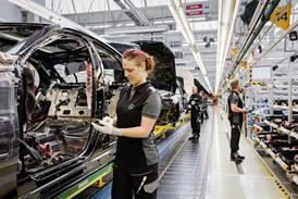
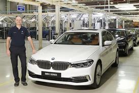
Once components are approved for production, many are transferred to ZF Lemförder’s car chassis modules plant at Diepholz, located 15km north of Dielingen. Here, lean production systems are deployed to produce parts that include upper and lower control arms for front and rear axles, along with other chassis components including toe links, tension struts, gear shifters and ball studs. Among the many vehicles fitted with these parts are the Audi A4, A6, A8 and Q7; BMW’s 5-, 6- and 7-Series, and the X3, X5 and Z4; the Mercedes-Benz S-Class; Rolls-Royce Phantom; Bentley Continental; Ford Falcon; Porsche Panamera; Saab 9-3x; and Opel’s Astra and Zafira models.
In total, the Diepholz plant, which produces production and aftermarket parts on the same machines, generated a turnover of €147m in 2009, with the help of 325 employees, around 215 of which are production-focussed. Components such as control arms are machined to produce a host of features that include precision bores for rubber bushes and ball joints. In terms of the latter, around 10 million ball joints are also machined and assembled at Diepholz every year.
Concentrating on control arms, four million of which are produced annually, these complex parts begin life as aluminium  forgings before being machined in line with topology optimisation that sees designers put material only where it is required. The parts must be a light as possible, but still fit for purpose. Each control arm design is subject to extensive strength analysis and shape optimisation scrutiny, together with fatigue validation and verification tests. Pendulum machining is a key manufacturing strategy. Typically, six control arms are machined in purpose designed fixtures while the next six parts are loaded by an operator in preparation for machining in an adjacent area on the machine bed. Chiron machining centres are used in this way and these models are well-represented on the shopfloor at Diepholz, alongside competitor machines such as Heller and SW.
Tolerances are typically in the realm of 0.005mm, with remote measuring stations located around the shop floor making it easy for operators to confirm accuracy compliance. The stations comprise Mahr 3D measuring systems fitted with laser, video and Renishaw touchprobe technology. There is also a temperature-controlled environment housing co-ordinate measuring machines such as a Mitutoyo FHN906.
The best practice principles exercised so effi ciently by ZF in Germany provide the benchmark for the company’s UK operations, where a major realignment has just been completed. In March 2010, ZF Great Britain and ZF Trading UK merged. While the former concentrated on sales and service to OEMs and the latter on independent aftermarket operations, the two have joined to become ZF Services, the combined operation having a total workforce of just under 200 people. Of these, about 150 are located at the company’s Nottingham facility, which houses a 6,500m2 workshop fi tted with a test rig that represents an investment of approximately £2.5 million. The remaining employees work at ZF’s Crick facility in Northamptonshire. Graham Truckel, former managing director of ZF Great Britain, now heads the new organisation, which is divided into six divisions: driveline, chassis, commercial vehicle technology, off-road technology, powertrain and suspension components, and steering technology. The merger is still subject to review before the fi nancial merger is fi nalised, a process scheduled for completion by January 2011. “Ultimately, the new arrangement makes it easier for clients to do business with ZF in the UK,” says Truckel. “Customers will receive improved services, a larger portfolio of products, complementary products, synergies in competency and a single point of contact.”
Quality is vital to maintaining the reputation of the ZF brand. The company might not offer the cheapest parts, for either OEMs or aftermarket buyers, but quality levels that see the parts fit first time, with durability and longevity, more than offsets any price differential. More than most others, these are ‘fit-and-forget’ parts.
The lean production lines are deliberately arranged to place machining and assembly operations in close proximity in order to reduce set-up and throughput times – three such areas at Diepholz are less than 18 months old. Using kanban systems, these areas are capable of product changeovers in between 10 and 15 minutes, where previously, the same operations could take between an hour, or even a whole shift. Even with this, new methods continue to come on-stream. At the time of visit, a number of new Heller MC Series highspecification CNC machining centres had recently been installed at a cost of around €1 million each. If the set up for control arms is impressive at Diepholz, it is probably matched by the manufacturing technology in place to produce ball joints, which exhibit three degrees of freedom to accommodate wheel movement. The process begins with ball pin turning, which incorporates eddy current crack detection technology. If the component is crack-free, final turning takes place, with all turning performed without coolant using Sandvik Coromant insert tips. The diameter is measured in-process so that the CNC machine can adjust to compensate for any appreciable tool wear. Tolerances are extremely tight, as any clearance or gap is will result in free travel and a noisy ball joint. The final operation sees the addition of threads using rolling techniques, rather than cutting, as this reduces the potential for crack generation.
Most of the ball pins pass through an automated case hardening line, although some are nitride-coated for corrosion protection, a process dependent on customer preference. Audi is one customer which elects to use the nitride coating. Ball joint assembly is also automated, including part marking and torque measurement operations. The ZF Lemförder plant at Diepholz runs 24 hours, five days a week.
Even the scrap bins are subject to close process scrutiny. Operators are instructed to deliberately damage the threads of faulty ball joints before dropping them into a scrap bin, which features apertures specially designed to prevent human arms from reaching inside to retrieve faulty components. The scrap bins cannot be removed from the racking due to padlocks, the keys to which are kept by an outside contractor which collects the toughened-steel parts for recycling.