Touch and go
The diversity of parts produced by automotive tier suppliers sees them use both contact and non-contact measurement techniques
Companies involved in contact and non-contact measurement operations have to make a fundamental decision about the type of coordinate technology they will utilise – either a contact technique involving a touch probe or a non-contact approach involving a camera system.
Both approaches, now well established, have relative merits. Contact techniques can be easily calibrated to provide traceability back to the basic SI unit of the metre through the use of physical test reference objects. Meanwhile, non-contact techniques are much faster and can gather huge amounts of data representing complete surfaces rather than just a number of points, but they can be susceptible to errors caused by the nature of the surface they are examining – for instance excessive reflectivity – or awkward geometry.
That brief summary is provided by Martin Dury, higher research scientist with the Mass and Dimensional Group at the UK’s National Physical Laboratory (NPL). Dury has been involved in recent project work carried out at NPL that has in turn been feeding data into an ISO technical committee – ISO/TC 213 – developing appropriate standardisation in the field of geometrical product specifications.
Calibration and environmental factorsIn practical terms what this means is that non-contact systems are likely to need much more careful calibration to take account of their immediate environment than contact systems. Factors that need to be taken into account include workpiece orientation, illumination, surface finish, material and colour, and temperature.
So how are companies out in the real world of automotive component manufacturing choosing between the two approaches and implementing them?
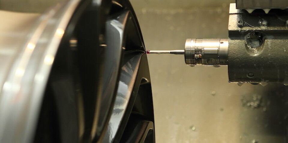
In Taiwan, SuperAlloy Industrial Company (SAI) is major producer of lightweight forged metal products including wheels and chassis components for numerous automotive OEMs. On the wheel rim production side, the company operates around 600 CNC machine tools – about a quarter of them lathes but the majority are milling machines.
Accuracy is a paramount concern with tolerances now at less that 0.02mm for the forged aluminium products. This is significantly more exacting that the corresponding figures from just five years ago when tolerances were in the range 0.05-0.10mm – a change brought about in large part by an increased demand for wheel rims with 3D visual effects rather than a completely flat surface. In order to meet these targets SAI is now an intensive user of on-machine metrology using touch probes from Renishaw. The 150 lathes, for example, are now fitted with Renishaw’s OLP40 touch probes, which use a wireless optical signal transmission to communicate their readings and are also specifically adapted to support turning processes.
Details of the devices’ capabilities are confirmed by Paul Street, senior executive with Renishaw’s machine tool products division. “In addition to being ultra-compact the probes have additional environmental protection to make them suitable for the harsh environment within the working envelopes of CNC lathes and turning centres,” he explains. “Protection includes additional sealing, steel battery cover/housing, a sapphire glass transmission window and a Teflon coated eyelid that covers the diaphragm below the front cap of the probe body.”
The milling machines, however, are fitted with Renishaw’s RMP60 touch devices. Street says that these are distinguished from their OLP40 counterparts by the fact that their wireless communication capability utilises radio transmission, which can operate over a range of up to 15 metres – three times that of the OLP40 devices. “This makes them suitable for larger machines and importantly for applications where line-of-sight between the probe and interface is not possible,” he states.
CT scanning gets the inside viewMeanwhile, Mindarika, based in Gurgaon, close to New Delhi, develops and manufactures multiple types of electrical switches and safety devices for automotive OEMs. The company, a joint venture between the Indian Minda Industries and Japan’s Tokai Rika, is a supplier to all OEMs in the four-wheeled and commercial vehicles segment.
Since April 2015 it has been using a Nikon Metrology XT H 225 ST CT scanning machine to implement non-destructive testing as an essential part of its quality control strategy. As deputy manager Amit Mishra explains, the previous destructive methods offered limited repeatability, low-level insight and often led to wasted materials and time. Instead, a system was required that was able to analyse internal structures and geometrical alignment. Key benchmarking criteria involved a “critical motion control switch for a mirror assembly, in particular simulating and assessing wear and tear and part ageing and its impact on vehicle safety.” With a new product introduction programme looming it was also paramount that the company be able to start operating a new system within four months.
CT scanners work by interpolating a test sample on a turntable between an X-ray emitter and a detector, which captures multiple 2D images of the object as it is rotated through 360°. The system then processes the data involved to create a 3D volumetric model from billions of ‘voxels’ – digital 3D cubes, each of which has its own x-y-z location and density. The model, which fully represents both the external shape and internal geometry of the part, can then be sectioned and investigated for compliance with various requirements including electrical connectivity, assembly alignments, material thicknesses and porosity.
[sam_ad id=17 codes='true']
The Nikon system that Mindarika selected has the ability to penetrate a wide range of materials and densities and can deal with sample sizes up to 50cm in diameter and 50kg in weight. That flexibility is particularly useful for Mindarika as the company’s products do vary greatly in size.
In actual use at Mindarika the system now serves as a sampling tool for implementing a series of essential routines on a regular basis. These include “periodic/cyclic checks, reconnaissance/investigative analysis of part failure in field trails and for ageing parts”. In consequence, says Amit, the company is achieving a new level of trust in the components that was not previously possible.
One current use of the system, Amit adds, is to investigate “two-wheeler and four-wheeler automotive switches and harnesses with the materials involved being plastic, aluminium and copper”. Compared with previous destructive test methodologies the company reports that the new system has proven particularly useful in the “study of switch engager inter-locks’ wear-and-tear during multiple cycles of usage to establish the lifecycle of products to support the study of vehicle safety norms.” Moreover in actual operation the system is proving much faster at producing useful information than previous methodologies. “The efficiency with which it can establish the cause and correction cycle is now better by as much as 30%, which means an overall productivity gain by a factor of more then 20%,” says Amit.
Nevertheless, the company regards itself as still only at the early stages of its exploration of the system’s potential and envisages much more intensive exploitation of its capabilities in the future. In its own words: “The installed system represents an established benchmark within Minda Group for NDT in automotive electronics. The aim now is to extend the capability and utilise the action of the system in the cause and correction cycle for product development and quality control of high performance products in the mechatronics area ie. micro mechanical and electronic components.”
Combining contact and non-contact techniquesOne company that is combining both contact and non-contact techniques into a single machine is tier two supplier of sheet metal components Berck, based in West Bromwich, UK. Around two thirds of the company’s output is automotive-based and comprises a mix of bracketry for use in engine compartments or wiring looms, and higher precision work to manufacture contacts for lights and other electrical equipment. Tolerances are +/-0.1mm in the first instance and +/-0.025mm in the second. Production involves stamping parts from coil 10-150mm in breadth and 0.1-3.5mm in depth, in materials including brass, mild and spring steel, copper, phosphor bronze and aluminium.
By the early part of 2016 the company was intent on a complete upgrade of its CMM capabilities. As quality manager Steve Bettridge explains, it had previously relied on two separate machines for contact and non-contact work but the latter was by then obviously becoming worn out while the former had actually been declared redundant and dismantled.
However, there is a marked disparity in the utilisation the two techniques. While some 95% of the throughput involves components that require only optical inspection, the other 5%, represented by steep-sided components such as fuse cups, necessitate the use of a touch probe.
Bettridge confirms that a key factor dictating whether a camera system or touch probing provide the appropriate technique is the geometry of the part.
He says that touch probing is necessary for “real 3D” work, most obviously for checking fuse cups and some bracketry – particularly those “with 90° angles”. The camera system suffices where measurements can be carried out from a single point-of-view.
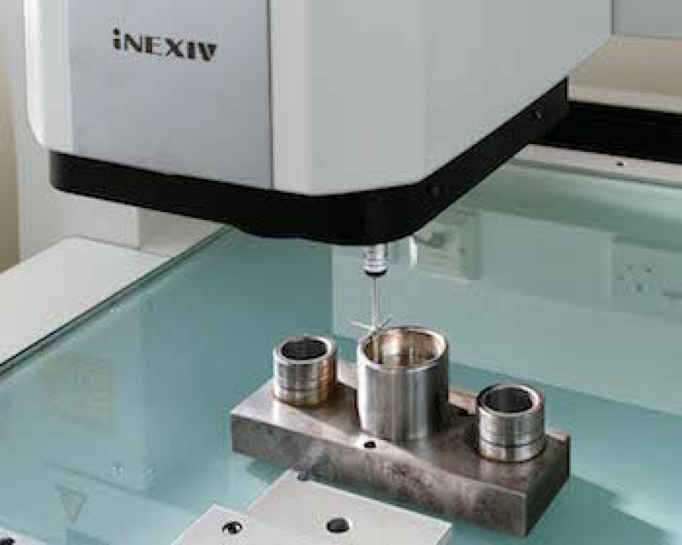
The solution was found in the form of a Nikon Metrology iNEXIV machine that combines both a camera system for video and still images and a touch-probing capability. The former, which utilises three different light sources, can measure not just shallow sheet metal components that can fit with its 450x400mm working area, but also steeper-sided fabrications. This is because of the fact that the Z-axis of the camera system possesses a 73.5mm working distance combined with an auto focus capability within its 200mm stroke. This provides what Bettridge terms a “virtual 3D” capability.
Meanwhile, the in-built companion touch-probing capability requires only one five-minute calibration routine each week to cover the use of any probe and also greatly increases the efficiency of actual metrology procedures. Now the 30 minutes the previous manual technique might have taken to inspect a batch of ten fuse cups is reduced to just a two-minute automated procedure.
The machine is located in an off-line quality control room and, says Bettridge, is used to check parts from the production area “every four hours”. Operation is a mix of automated routines to check objective criteria such as dimensional accuracy, and used by trained personnel viewing images generated by the camera system in real-time to identify factors requiring a more subjective judgement. One such that Bettridge mentions is a much enhanced ability to estimate tool wear by examining the surface quality of parts.
But the technical capabilities of the machine are not its only attribute. Bettridge notes that it also satisfies a business case for compliance with customer demands. They can have similar machines in-house, he observes, and its necessary for Berck to have the same level of capability itself.
Supplier of automotive steering systems Nexteer looked to its own resources to provide itself with an automated inspection system to check the quality of the through-hole soldered joints used to mate printed circuit boards with electric motors. Deterred in part by the cost of commercially available systems it set out to develop its own that is now in use across the whole of its operations worldwide. The system utilises four led light sources – white, blue, red and green – to illuminate assemblies placed inside its cabinet from different angles.
Marcin Zywczok, manufacturing engineer at the company’s plant in Tychy in Poland, explains that an essential step in the assembly of the column and rack electrical assist steering systems the company produces is to solder the motor to the controller, producing what the company refers to as the ‘powerpack’. This process is automated, after which the assemblies are transported to the inspection station. An international specification, IPC 610, which stipulates appropriate inspection criteria, does exist, he says, but it relates only to visual routines carried out by people. So the Nexteer system aims to satisfy those requirements but by means of an automated optical procedure.
The inspection routine itself takes about 15 seconds per powerpack, though the bulk of that time is taken by the manual loading and unloading of the assemblies. The actual inspection process takes “just a few seconds” and involves capturing four separate photos that are formed into a single composite image in the control and inspection software. That compact timescale is crucial to the fact that the system is used on a 100% inspection basis and not for periodic sampling.
Zywczok says one factor the system verifies is that the solder material is distributed evenly over each solder pad. Another is that the terminal of the motor, which protrudes through the controller, is similarly consistently coated. The shape and size of each solder joint are also inspected.
Though the process is completely automated a degree of human intervention is allowed for. Zywczok explains that if the system starts to reject parts at a suspiciously high rate – around 3% is the trigger figure – then an operator will intervene to check visually whether or not the parts are genuinely non-compliant, since it is possible for the system to be overly stringent in its operations. Nevertheless, the system is now a well-established element in the company’s quality control regime, which it regards as fully mature and reliable.