Make way for X-ray
X-ray systems can be used in automotive to enhance quality control and traceability while reducing waste
 The ability of X-ray radiation to penetrate engineering materials permits inspection systems to image and measure hidden features. The automotive industry uses this technology as part of a growing need for Six Sigma quality assurance and product traceability to limit liability and improve product quality.
Often, a single X-ray scan can reduce the need for inspection stations because it can perform a final quality check after packaging, rather than at key points along the production line.
X-ray technology is ideal for detecting faults such as cracks and welding defects in automotive castings. However, according to UK-based supplier 3DX-Ray, inspection with 2D and 3D X-rays also suits a whole host of automotive industry applications, including complex assemblies and micro-electromechanical systems; coatings and features within catalytic converters; intercoolers; heat exchangers; fuel injection systems; exhaust systems; suspension parts; braking systems; and engine mounts and coolant hoses, amongst others.
Data for quality & process control
As a non-destructive technology, X-ray systems minimise waste and scrap while providing a tool that can improve the understanding of the manufacturing process, says 3DX-Ray. Using sophisticated image capture and processing software, operators can not only ‘see’ sub-millimetre details inside an object, but can also measure and analyse them, providing valuable data for quality and process control.
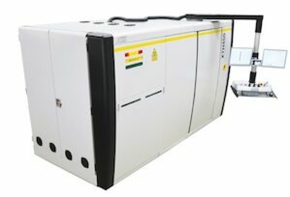
As an application example, the MDXi x-ray system from 3DX-Ray is capable of measuring substrate coatings or multiple wash-coats to identify defects such as gaps and overlaps that could lead to the failure of a catalytic converter. It is said to provide 100% control at full production line speed.
The layering process of the wash-coats on a catalytic converter is intricate and it is imperative that it is done correctly. If errors are introduced into the manufacturing process, expensive materials can be needlessly wasted and the performance of the catalytic converter substantially reduced.
A software suite is provided with MDXi for analysis, data tracking and record recovery. Images can be viewed visually and/or used for automatic analysis, while feedback from the system can be relayed rapidly to control the manufacturing process.
Micro-focus computed tomography
Turbocharger inspection is another application that can benefit greatly from the use of X-ray inspection technology, as BorgWarner Poland can testify. Here, a micro-focus computed tomography (CT) system from Nikon Metrology is being used to improve the R&D of turbochargers for passenger cars, light trucks and commercial vehicles. The 450 kV X-ray system is able to penetrate the dense materials used in turbocharger production. In addition, dimensional data for specific components is acquired more quickly than is possible with a co-ordinate measuring machine (CMM), both from external and internal dimensions, says Nikon.
BorgWarner’s three production plants on the Podkarpacki Science and Technology Park in the Rzeszów area of Poland include a production facility with the capacity to produce more than 1m turbochargers annually. A new Technical Centre opened recently on the same campus to provide application engineering and design, simulation, testing and validation, as well as material analysis. The Nikon Metrology XTH450 micro-focus CT system was installed in February this year.
“Before we put an assembled turbocharger onto an engine emulator for endurance and thermo-mechanical testing, we need to check the quality of the individual components and sub-assemblies,” says Łukasz Krawczyk, team leader and material laboratory manager. “Previously we did this by sectioning sample castings and machined prototypes, and checking them on a CMM. But that meant we were wasting valuable prototype or pre-production components. Additionally, the parts we were testing were representative examples from the same batch, rather than the ones we actually inspected, which were of course destroyed.”
Detailed inspection
Using CT, it is possible to ascertain the location and size of a void (or crack emanating from it) and determine the likely cause of the fault and whether it is due to the type or quality of the material, or the component design. Furthermore, bearing assemblies can be X-rayed to check that all of the components are present, avoiding the cost of dismantling, while the electron beam weld that joins the impeller to the shaft can be inspected to check for porosity and mechanical integrity, a job that is impossible to do visually.
So what of wheels? Surely there is an application for X-ray inspection here? Indeed, Yxlon offers various systems for analysing cast wheels depending on the application and flaw pattern involved. According to the company, its Y.MU231 X-ray system is best suited for series wheel inspection. The wheels can be fed in unfinished and in mixed-mode operation. The system identifies the wheel model automatically and inspects it according to customer specification, with blowholes and foreign bodies categorised as individual flaws or as a cluster.
Yxlon also has solutions for parts such as pistons. In light of the great amount of stress placed on lightweight aluminium pistons for diesel engine passenger cars, even tiny production flaws such as salt core residues in the cooling channel can result in substantial damage later in service. The company’s Y.HDR X-ray system makes common anomalies visible, for instance blowholes and blisters, but also cracks and residues in the salt core and inclusions of foreign materials.
Geometric measurement of inner structures
For engine blocks, cylinder heads and chassis parts, the Y.HDR system can deliver information on the verification of blowholes and pores, the geometric measurement of inner structures and wall-thickness analysis. [sam_ad id=17 codes='true']
At bearing manufacturer Hartford Technologies of Rocky Hill, Connecticut, the challenge is to ensure that each bearing has the appropriate ball count inside. Hartford makes 20,000 ball bearings per eight-hour shift, and since there are two shifts per day running five days per week, the monthly production totals 800,000 units. The bearings are used in steering columns.
Each steering column requires two ball bearings to eliminate friction in the steering wheel. If a bearing does not have the correct number of balls, there is an increased risk of binding in the steering column. As a continuous improvement effort, Hartford purchased an Eagle Pack 240 from Eagle Product Inspection after consultations and product testing proved that X-ray technology could perform the necessary inspection.
The Eagle Pack 240 inspects seven different sizes of bearings running single file on a belt to verify the proper ball count in each. As the ball bearings pass through the X-ray machine, the number of balls within is analysed for the appropriate count based on the requirement for each size of bearing. Bearings containing too few or too many balls are rejected from the manufacturing line. The Eagle X-ray system has eliminated the need for an additional employee to visually inspect each bearing, neutralising the potential for human error.
CT is fundamentally a simple process. An object is placed on a rotating stage between an X-ray source and a detector, which acquires simple 2D radiographic images of the object as it rotates. After the object has turned through 360°, the 2D X-ray images are reconstructed into a 3D volumetric map of the object. Each element is a 3D pixel (voxel) which has a discrete location and density. Not only is external surface information acquired, as with a 3D point cloud from laser scanning, but data on internal surfaces is also revealed; by mapping the density, information is provided on what lies between the surfaces.
The X-ray tube is at the core of a CT system. Several different open or closed tube designs exist, but essentially an X-ray source consists of a cylinder in which there is a filament (similar to a light bulb) at one end, together with a high-voltage cathode and anode, a magnetic lens and a metal target, normally made from tungsten.
Before they leave, the electron beam is focused on the target material using an electromagnetic lens. The electrons hit the target and 99% of the energy is expended in heating it. Less than 1% produces X-rays that are generated in a cone beam from the target.
The higher the voltage applied, the more energy is in the beam, the more power is transferred to the target, the larger the spot size and the greater the X-ray power produced. However, a limitation of CT in industrial applications is that high material density, especially metals, attenuates the X-rays.
According to Nikon Metrology, many system suppliers only offer micro-focus sources up to 225kV, while its own more powerful sources are mini-focus, producing more X-ray flux but with a spot size an order of magnitude larger, reducing the accuracy of the data collected. A micro-focus source is needed to acquire accurate and detailed CT data for most high-accuracy industrial CT applications.


