Computer-aided solutions
The latest CAD/CAM systems are streamlining the design-to-manufacture process in parts production
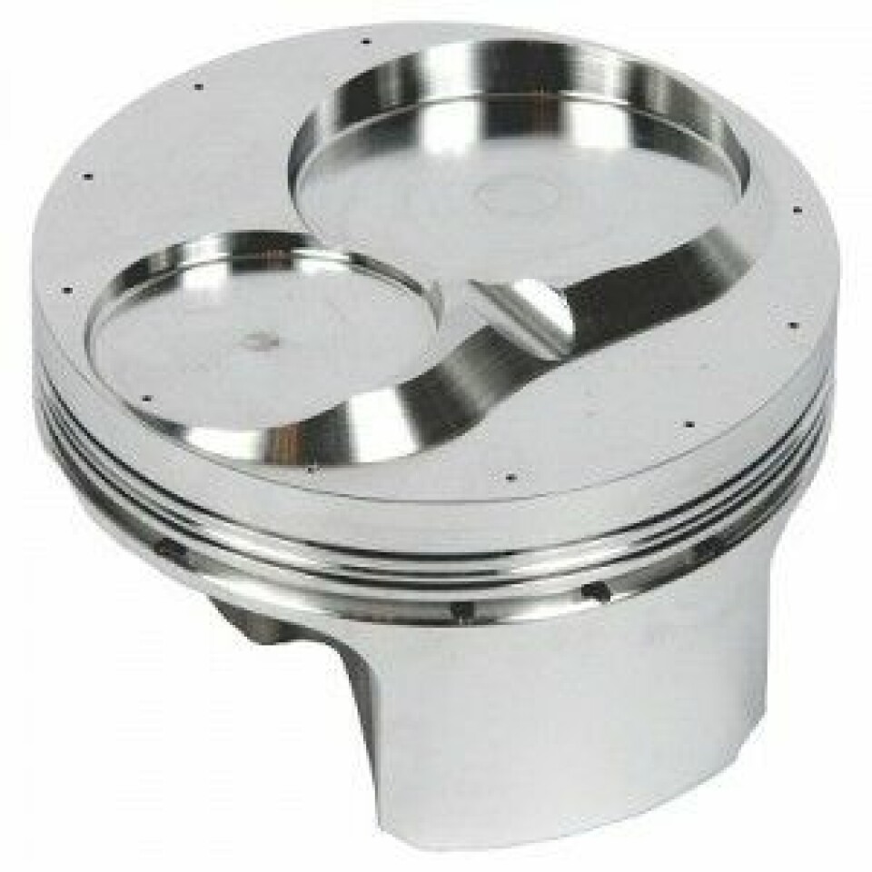
Customer response time is at a premium at Ross Racing Pistons. The California-based company produces aluminium pistons for various custom cars including drag racers, making up to a thousand units a week in response to 40-50 different orders. Production involves a sequence of computer numerical control (CNC) machining operations, starting with one of the 95 forged aluminium blanks (from 1.5-6.8 inches in diameter) that the company maintains as essential raw material. The process ends with one of the 900 or so variants that can be dictated by differences in end application, cylinder-head geometry and compression ratios.
While those production procedures are relatively fixed, the company identified one major inefficiency in the whole order-to-despatch sequence that it could address: the time its computer-aided manufacturing (CAM) software required to process design data into CNC programs that could drive operations on its shopfloor. Its previous CAM system used the tried-and-trusted but quite old C++ language, which meant that 200 hours of programming time were required each week to support its machining processes. Now, though, that total has been slashed to just 30 hours a week, with the programming time for all the procedures for a specific part taking 20 minutes. The key to enabling that, as chief engineer Nicholas Plantus confirms, has been the acquisition of a new CAM software system: Esprit from DP Technology.
Keeping software simpleA crucial underlying factor, Plantus explains, is that the software uses the Microsoft Visual Basic for Applications (VBA) programming language, a much more modern system that is easier both to learn and implement. This has enabled the company to accelerate the creation of 'macros' – effectively, pre-recorded sequences of the machining operations required to create particular parts. Its straightforward nature also means that the company is not tied in, as previously, to the skills of a specific, hard-to-replace programmer.
In fact, it is not only the CAM system which is involved. An important supporting factor is that the company maintains a library of standard piston shapes in the Pro/Engineer 3D computer-aided design (CAD) modelling format, and these form the basis of all subsequent CAM and machining work, as well as of essential design operations such as calculation of piston volume displacements. This is the case even if a customer can only submit a paper drawing or, as sometimes happens, a physical model of the relevant engine's combustion chamber. Here, the most approximate standard model is selected from the library and amended as required.
What follows is a compressed five-step process in which programmers need only supply numerical data and make selections from various options presented by means of on-screen menus to create the required piston geometry. That usually means defining between ten and 12 features on each part – a process that takes five minutes at most. The programmer then identifies the required machining operations, assigns them to the appropriate machine and chooses the necessary tool. But the actual machining code is generated automatically in the software.
Intended machining procedures can also be simulated on-screen and a virtual representation of the part they will produce compared with the initial reference CAD information. Details can be checked very easily by positioning the cursor over a part to generate a read-out of its dimensions. Catching mistakes before they happen, Plantus remarks, is now much easier and so scrap rates have been reduced.
Use of the Esprit system has also provided some other, more intangible but still perceptible benefits. The company is no longer, for instance, reliant on a single individual to carry out its CAM programming. It currently has two such staff, both of whom already have enough free time to be able to carry out other tasks such as setting up machines on the shopfloor. The company also confirms that the system's ease-of-use would facilitate the training of additional staff, if desired.
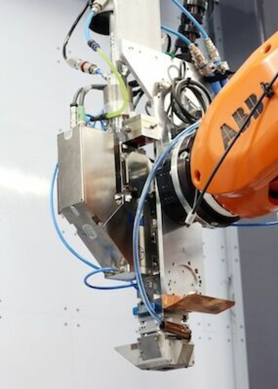
Using CAM for surface treatmentsOn the other side of the Atlantic, a recent CAM software development project has enabled a small, specialist UK company to offer an enhanced robotic surface treatment procedure to a range of clients including Formula 1 (F1) racing teams. Sandwell UK, based in Towcester, collaborated with the Manufacturing Technology Centre (MTC) in Coventry to develop a means of increasing both the speed and consistency of robotic shot peening. The process involves firing small metal balls at a workpiece at very high speed to increase compressive stresses in its surface, which in turn provides enhanced surface qualities offering increased protection against crack propagation, for instance.
Colin McGrory, technical director for Sandwell, confirms that robotic shot peening is a well-established procedure for improving the resilience of components that are likely to encounter tough working conditions. As such, the technique is one which Sandwell is familiar with and has implemented over recent years with increasing degrees of sophistication. McGrory explains that the company has progressed from carrying out the process as just a two-axis operation, then to four and now to eight by means of a six-axis ABB robot with the workpiece mounted on a table and a further two axes of movement. Nevertheless, he says the company remained dissatisfied with the process for a number of reasons.
New CAM software has reduced machine programmming time at Ross Racing Pistons from 200 to just 30 hours per week
Essentially, McGrory explains, the method of programming the robot was unable to generate a smooth operating procedure; the shot-peening process itself was intermittent, meaning that it was both less effective and more time-consuming. The basic requirement is to create a computerised 3D surface model of the part that is to be shot-peened, from which the program that actually controls the movements of the robot can be generated. Sometimes this can be effected by processing CAD data supplied by a client, but on occasion this may not be possible, either because no relevant CAD data exists or a client cannot provide it for reasons of confidentiality. The task frequently has to be accomplished by scanning a part with a non-contact sensor that can record all the details of its surface geometry.
McGrory says that Sandwell used to do this with a conventional laser system but found the results unsatisfactory. The scanning procedure, he explains, would “step across” the surface of the part and therefore generate a program that would make the robot operate in a correspondingly intermittent manner. “It generated a series of points and we had to interpolate between them,” he explains. However, to be really effective, shot peening needs to be carried out in a continuous, “totally fluid” manner, and so the company set out to find a way to achieve this goal.
Scanning for a solution
This led it to the MTC and a collaborative project under the terms of the UK Government's High Value Manufacturing Catapult initiative which has succeeded in solving the problem. McGrory says the solution has two crucial elements. The first of them was the identification of an appropriate new scanning procedure using “structured light” in which the workpiece is illuminated with a pattern of alternating light and dark stripes. The second is that the resultant data is then processed in an offline PC using a software system developed specifically for the purpose. Crucially, when the information generated by that procedure is fed through to the robot's own controller, it enables the robot to carry out shot peening in the required continuous manner.
The new system was commissioned early in 2015 and, according to McGrory, is demonstrably superior to what was possible previously. Operation is now not only continuous but the shot-peening head on the robot is also consistently normal to the workpiece surface, improving quality. Furthermore, the whole process is reliably repeatable and therefore verifiable. It is also quantifiably faster. A complete scanning and shot-peening process that might previously have taken four to five hours can now be accomplished in just one hour, he confirms.
The development, McGrory concedes, is unlikely to make shot peening more frequent in volume manufacturing, but it does greatly enhance the potential for its use in environments characterised by low volume and high variability. For Sandwell, that certainly opens up the possibility of looking beyond the world of F1 and finding opportunities in the market for high-end, short-run road cars.
