


Lincoln Electric’s Tim Hurley and Michael Klee look at how the number of aluminium structures in BEVs can create new challenges to those unaccustomed to welding the metal

Aluminium welding challengesIncreased thermal conductivity, surface oxides and limited column strength in small-diameter wires make the welding of aluminium significantly different from welding steel. More attention needs to be paid to critical details such as part cleanliness, control of heat input, weld sequence, thermal expansion/contraction and alloy selection of filler metals. Special wire feeders and a higher level of maintenance of the wire feeding system may also be required. These challenges can be easily overcome if the proper knowledge and tools are applied during the early stages of process planning and product development.
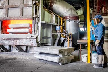
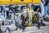
Systems designed for productivity and qualityThe design of an automated welding system for aluminium should not start with the welding operation only. Upstreamfrom the cell, attention should be paid to assure component part consistency. From machined castings and precision cut extrusions, to part washing and material handling equipment, the welding operation requires clean, repeatable parts to maintain an efficient, reliable joining process.
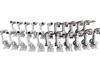
Filler metal alloys and wire feedingMatching the base material and filler metal properties is critical for mechanical integrity and weld appearance in aluminium welding operations. In addition to the most common 4043 and 5356 filler metal alloys, Lincoln Electric can create specific filler metal alloys from pure aluminium ingot and then draw a finished wire product with precise specifications relative to chemistry, diameter, hydrogen levels and surface conditions. That wire can then be packaged in bulk Gem-Paks for continuous wire feeding of up to 300 lbs. in one package. The Gem-Pak achieves maximum uptime by limiting the number of wire changes needed in an automated system to no more than one or two per month.
The unique winding and packaging of the Gem-Pak also reduces the amount of pull force required to feed the aluminium wire, thus increasing the usable wire speed range and maximising productivity and wire deposition rates.
Feeding of the soft, aluminium filler metal through a robotic torch is critical to creating a repeatable, robust manufacturing process, so it’s best to implement a servo-driven push-pull system with drive rolls designed for a specific aluminium wire size. Polished “U” groove drive rolls, plastic wire guides and contact tips designed specifically for aluminium wire diameters should all be part of the feeding system to prevent marking or shaving of the wire. Lincoln Electric’s Autodrive SA feeding system incorporates two servo-driven push-pull motors and is adaptable to most major robot brands. In addition to providing precise wire speed control, this innovative feeder also uses Touch-Retract technology to ensure positive arc starts with every weld.
Welding process selectionAluminium’s high level of thermal conductivity makes it susceptible to thermal expansion and greater crack sensitivity. Because of this, welding process selection is very important to ensure a controlled level of heat input without overheating the parts. The traditional philosophy for welding aluminium “hot and fast” should be replaced with a “controlled and robust” process that can produce repeatable results under normal manufacturing variations.In the past, gaps and part variation were always a concern with thin material (less than 3.0 mm thick) because the lack of base material mass would mean a high heat input process could burn through or over-penetrate. The introduction of AC Pulse within the past three years has meant that consistent results are possible when welding on material as thin as 1.0 mm. Because AC limits the amount of penetration into the base material and more efficiently melts the filler metal, its application allows for higher wire speeds, higher deposition rates and resulting higher travel speeds when compared to traditional DC pulse processes. On 2.0 mm base material for example, travel speeds can be increased by as much as 35% while still maintaining a high tolerance for gaps and fit-up.
On material more than 3.0 mm thick, a variety of pulse waveforms and other DC welding outputs can provide the controlled heat input necessary to assure consistent penetration while still providing tolerance for joint variation. These aluminium pulse modes are designed specifically for 4XXX or 5XXX series wires because the chemistry and conductivity differences between these wires give them vastly different operating ranges and characteristics. Additional techniques, such as the use of weave patterns, can also be successful with aluminium applications, as these weaves allow for greater tolerance of joint variation and the ability to change welding parameters to accommodate dissimilar material thicknesses.
Consistent heat input and a stable arc are important for producing high-quality, high-productivity welds with material more than 6.0 mm thick. Lincoln Electric’s Power Mode is a DC welding output that combines control of both current and voltage to produce a constant level of power (kilowatts) in the welding arc. This constant power level creates a very stable arc at high energy, thus providing a more consistent penetration pattern on heavy material. Cycle time and weld sequence
Regardless of the material thickness, part of the cycle time should be dedicated to properly filling the weld crater created by the penetration of the welding arc. These crater fill procedures can add 1 to 2 seconds of cycle time per weld and should be accounted for in the weld process analysis. Delay times and reduced heat input procedures are critical to assuring that no crater cracks are created at the weld end.One other consideration that adversely effects cycle time on aluminium components is making the welds in a proper sequence in order to distribute the heat and control distortion. This will typically mean making welds in a non-linear sequence that increases the number of robotic air moves and part rotation. This increased time, however, will lead to more repeatable weld conditions and will help to minimise distortion.
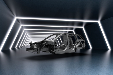
ConclusionThe increasing number of aluminium components on EV structures can cause new challenges for OEMs and tier one suppliers that have previously produced primarily steel components. These challenges can seem daunting, but they’re not insurmountable. They do require better planning and preparation before launch, as well as more attention to detail once the projects are in production.
www.lincolnelectric.com/aluminum
Authors: Timothy J Hurley is the global segment manager and Michael Klee is a welding engineering technologist at Lincoln Electric